A star-delta starter limits starting current, but it does not by itself stop a motor from running under damaging overload conditions. By the end, you will know what the thermal relay senses, where it belongs, how to set and reset it, and which pump or motor faults need additional protection.
Key takeaways
- Set relay current from the motor nameplate, not the motor horsepower alone.
- Choose trip class 10 for normal starting; use higher classes for long acceleration.
- Install the relay where it measures the motor’s actual running current.
- Use manual reset when an unexpected restart could endanger people or equipment.
What protection does the thermal relay add to the starter?
An automatic thermal relay adds sustained-overload protection: it senses excessive motor current and opens the control circuit before heat damages the windings. Star and delta contactors only connect or disconnect the motor, while the timer only controls when the circuit changes from star to delta.
Neither device decides that the motor has been drawing too much current for too long.
The relay responds to conditions such as:
- Mechanical overload from excessive pump head, a blocked impeller, or bearing resistance
- Low supply voltage that increases motor current
- A stalled rotor or failed acceleration
- Loss of one phase, which makes the remaining phases carry damaging current
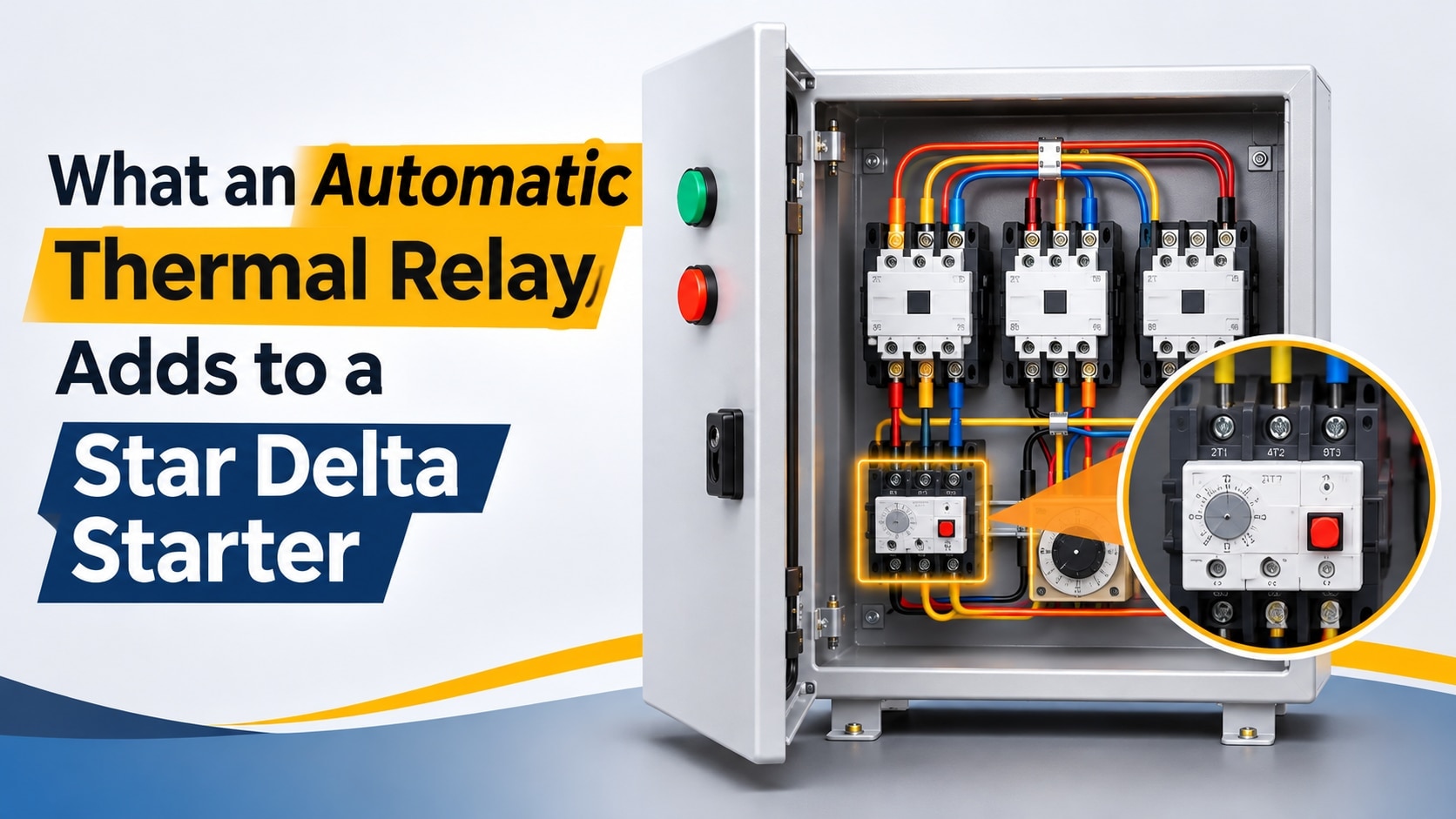
Wire the relay’s normally closed auxiliary trip contact into the complete star-delta control circuit. A trip must release the main, star, and delta contactor coils and stop the timer sequence; connecting it to only one branch can leave another command energised.
The relay can stop overheating, but it does not clear a short circuit. Keep correctly rated fuses, an MCB, or a motor-protection circuit breaker upstream for high fault current. Star-delta thermal relay protection therefore complements, rather than replaces, short-circuit protection.
Set the relay for its installation point: a main-line relay relates to full-load line current, while a delta-circuit relay carries about 0.58 times that current.
Where should the relay be installed, and how is its current setting calculated?
Use the motor nameplate full-load current as the starting point, then match the setting to the relay’s position. An automatic motor overload relay in the main line carries the motor’s full line current, while a relay connected in the delta winding circuit carries only about 0.58 of that current.
| Position | Current through relay | Normal adjustment |
|---|---|---|
| Main-line installation | Motor line current | Nameplate full-load current |
| Delta-circuit installation | About 0.58 × line current | About 0.58 × nameplate full-load current |
For example, a motor marked 16 A requires a main-line setting near 16 A. A delta-circuit relay for the same motor requires about 9.3 A. Do not apply the 0.58 factor to a main-line relay; the resulting low setting can cause nuisance trips during normal running.
Check the manufacturer’s wiring diagram before choosing the position, because the relay must monitor current in every running phase and remain coordinated with the star and delta contactors. Select an adjustment range that places the calculated value near the middle, rather than at the extreme end.
Wire the relay’s normally closed trip contact into the control circuit so an overload drops out both contactor commands and stops the timer sequence. A relay connected to only one control branch can leave another command energised after a trip.
Set from the nameplate, not the horsepower label; supply voltage, efficiency, and power factor affect the actual full-load current.
How do trip class and reset mode affect motor safety?
Select the trip class from the motor’s actual acceleration time, not from its horsepower. Class 10A trips in about 2–10 seconds and class 10 in 4–10 seconds at 7.2 times the setting current; these suit a pump that reaches speed quickly.
A high-inertia load that needs longer acceleration may require class 20 or 30, with approximate ranges of 6–20 and 9–30 seconds.
| Load or operating condition | Suitable choice | Safety consequence |
|---|---|---|
| Quick-start pump | Class 10A or 10; manual reset | Trips promptly during a stalled impeller or overload; manual reset prevents a faulted pump restarting |
| High-inertia load | Class 20 or 30 after measuring acceleration time; manual reset | Avoids nuisance trips during starting without disguising a genuine prolonged overload |
| Unattended motor | Class matched to acceleration; manual reset or electrically latched fault | Prevents automatic re-energisation after a trip; use automatic reset only when the installation prevents hazardous cycling |
Automatic reset reduces site visits, which is one of the 10 hp thermal relay benefits, but repeated trips can start and stop an unattended motor until its windings, coupling, or pump are damaged. For a pump, manual reset is the safer default, especially where inspection is needed.
Do not select class 30 merely to stop nuisance tripping. Check the pump’s acceleration time and investigate high head, blockage, low voltage, phase loss, or a failed star-to-delta transition before increasing the class. A thermal relay also will not detect every dry-run or loss-of-prime condition; add underload, level, pressure, or flow protection where required.
What happens during a failed transition, stalled motor, or phase loss?
A failed star-to-delta changeover must leave both power contactors de-energised. The overload relay’s normally closed trip contact belongs in the common control circuit, ahead of both star and delta coil paths, so one trip drops every contactor and stops the timer sequence.
Electrical and mechanical interlocks must also prevent the star and delta contactors from closing together; overlap can create a phase-to-phase short circuit.
Set the transition timer from measured acceleration, not a standard time. A changeover before the motor reaches speed causes a heavy current surge and possible overload trip; excessive time in star leaves the motor with low torque and can overheat it. A failed timer or welded contactor requires a stop-and-inspect condition, not another automatic attempt.
A mechanical overload, blocked pump, tight bearing, low voltage, or stalled rotor produces sustained high current. The relay should open the control circuit, latch the fault indication, and require manual reset when an unattended restart could be hazardous.
Repeated starts also accumulate motor heat, so add a restart inhibit that allows cooling and limits the number of starts per hour specified by the motor manufacturer.
For phase-related faults, use a phase-sensitive overload relay or a separate phase-failure and under-voltage relay. It should trip on phase loss, severe voltage imbalance, or wrong phase sequence before the motor runs single-phased. Keep HRC fuses or a correctly coordinated circuit breaker for short circuits; the thermal relay cannot interrupt that fault current.
What should you verify before specifying a relay for a 10 HP installation?
A 10 HP label is not enough to specify an automatic motor overload relay. Obtain the motor nameplate full-load current, running voltage, six-terminal star-delta connection, starting duty, and driven load. Confirm that the relay’s adjustment range places the required current near its middle, not at an extreme.
Check these installation details before ordering:
- Identify whether the relay sits in the main line or delta circuit. A main-line relay is set to the nameplate current; a delta-circuit relay carries about 0.58 times that current.
- Check the panel’s actual ambient temperature, enclosure ventilation, dust, humidity, and exposure to direct sun. In Coimbatore, a hot outdoor panel or dust-blocked ventilation can reduce thermal margin, so apply the manufacturer’s ambient derating.
- Match the relay’s trip class and reset mode to the pump’s acceleration time and whether the motor runs unattended.
- Coordinate the relay with the contactors, HRC fuses, MCB or motor-protection circuit breaker, and available short-circuit current. The relay does not interrupt fault current.
- Wire its normally closed trip contact so both star and delta coils drop out and the timer cannot restart the sequence automatically.
- During commissioning, record running current in all three phases, verify phase sequence, measure star-to-delta transition, and investigate imbalance or repeated trips.
| Relay location | Adjustment basis | Main risk |
|---|---|---|
| Main line | Motor nameplate full-load current | Applying 0.58 causes nuisance trips |
| Delta circuit | About 0.58 × nameplate current | Setting at line current weakens protection |
These checks capture the automatic thermal relay advantages for star delta starters in Coimbatore. MAG STARTERS (PRAVIN ENGINEERING) - 08048068970 can verify the relay location and setting against the motor and panel wiring.
Related products
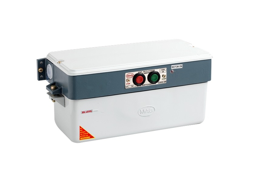 | OIL IMMERSED MOTOR STARTERS STAR DELTA - AUTOMATIC THERMAL RELAY 10HP ₹12890 • Ranging from 5 HP to 50 HP • Contacts made of Electrolytic Copper with Double Break System, Ensure long life and Better Conductivity • No Volt coil... View product → |
 | Air Break Starters Air Break Star Delta Automatic Motor Starter 15HP ₹10550 We are one of the distinguished manufacturers and suppliers of Air Break Star Delta Automatic Motor Starter. View product → |
Frequently asked questions
What protection does a thermal relay add to a star delta starter?
It provides sustained-overload protection by sensing excessive motor current and opening the control circuit before overheating damages the windings.
Where should the thermal relay be installed in a star delta starter?
Install it where it measures the motor current correctly, then set it from the motor nameplate current and the selected starter configuration.
How do trip class and reset mode affect motor safety?
Trip class determines how quickly the relay responds to overload during starting, while reset mode controls whether the motor can restart automatically after cooling.
What happens during a failed star-to-delta transition?
The motor can lose acceleration, draw excessive current, or stall; the overload relay should interrupt the control circuit if the condition persists.
What should you verify before specifying a relay for a 10 HP installation?
Check the nameplate current, supply voltage, motor starting time, relay installation position, trip class, reset mode, phase-loss protection, and contactor compatibility.
Related products
 | Oil Immersed Starter CODE NO 033 Oil Immersed Starter Star Delta - Handle Type 10 HP ₹7710 • Ranging from 5 HP to 40 HP • Electrolytic Copper Contacts with Double Break System, Ensure long life and Better Conductivity • Changeover from Star... View product → |
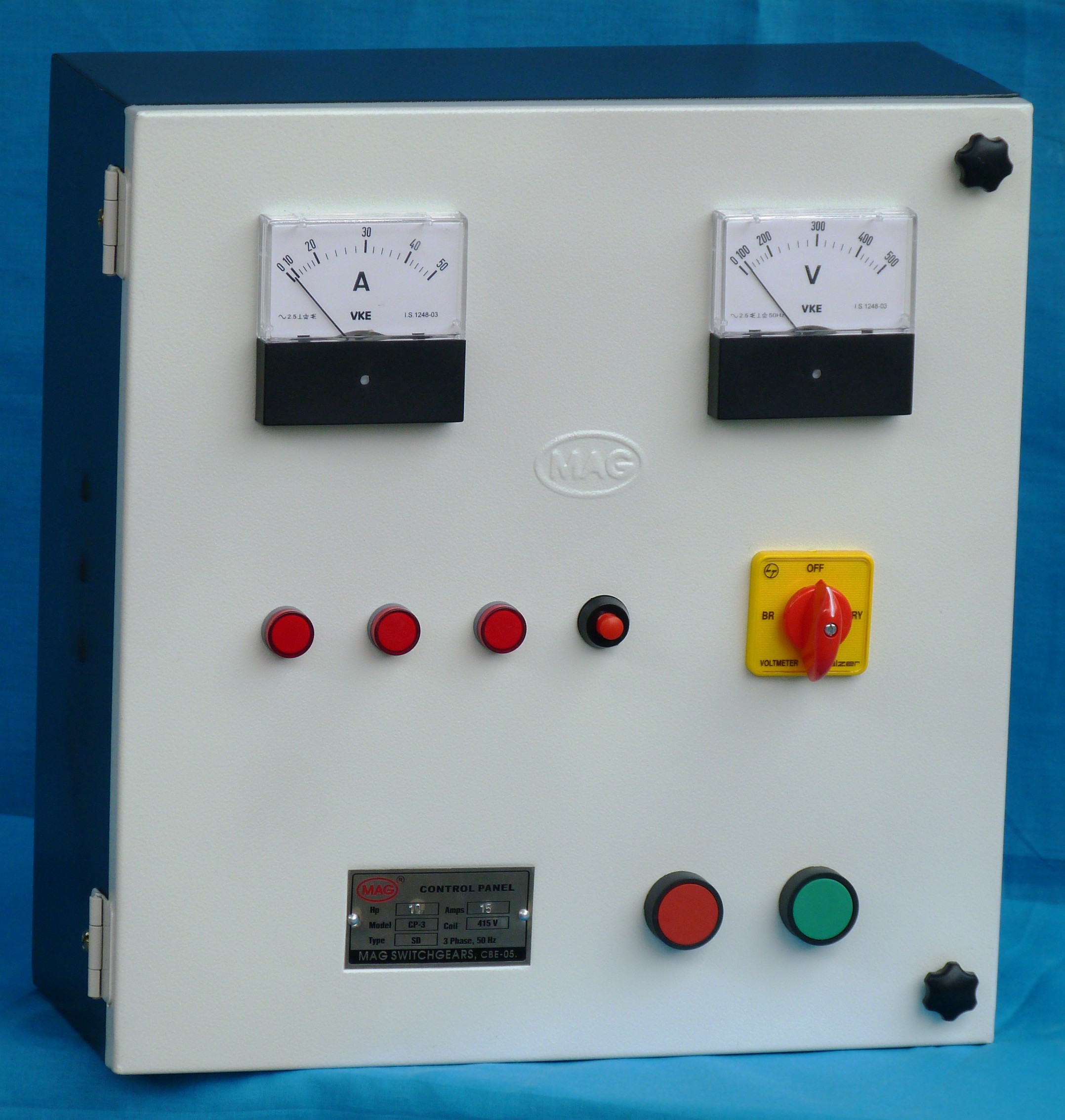 | Control Panel for Submersible Pumps Three Phase Panel - Star Delta 15HP ₹22010 • Ranging from 5 HP to 25 HP • Suitable for Bore-well Submersible Pumps • Analog Type Amps Meter & Volt Meter (Big-Square Type) • Bimetal Thermal... View product → |
 | Submersible Control Panel Three Phase Star Delta Control Panel 20HP ₹24270 Features: Ranging from 5 HP to 25 HP Suitable for Bore-well Submersible Pumps Analog Type Amps Meter & Volt Meter (Big-Square Type) Bimetal Thermal... View product → |
MAGIC PUMP CONTROLLER PANEL 1+3 STAR DELTA PANEL MAGIC 15 HP ₹34270 1+3 STAR DELTA PANEL MAGIC UP TO 20 HP MAG Three Phase Panel Magic Model. View product → |
Keywords