A submersible motor can keep running while one phase is weak, a winding is overloaded, or the pump has lost its water load. By tracing what the panel measures, which fault each device handles, and how settings are selected, you can judge whether a proposed panel will actually protect your motor rather than relying on its horsepower label.
Key takeaways
- Set overload current from the motor nameplate, not the 10 HP rating alone.
- Use phase-loss, imbalance, dry-run, and short-circuit protection for different faults.
- Test each trip function with simulated faults before connecting the pump.
- Choose DOL, star-delta, analog CT, digital, or auto-start controls by application needs.
What the CT measures before a submersible motor is damaged
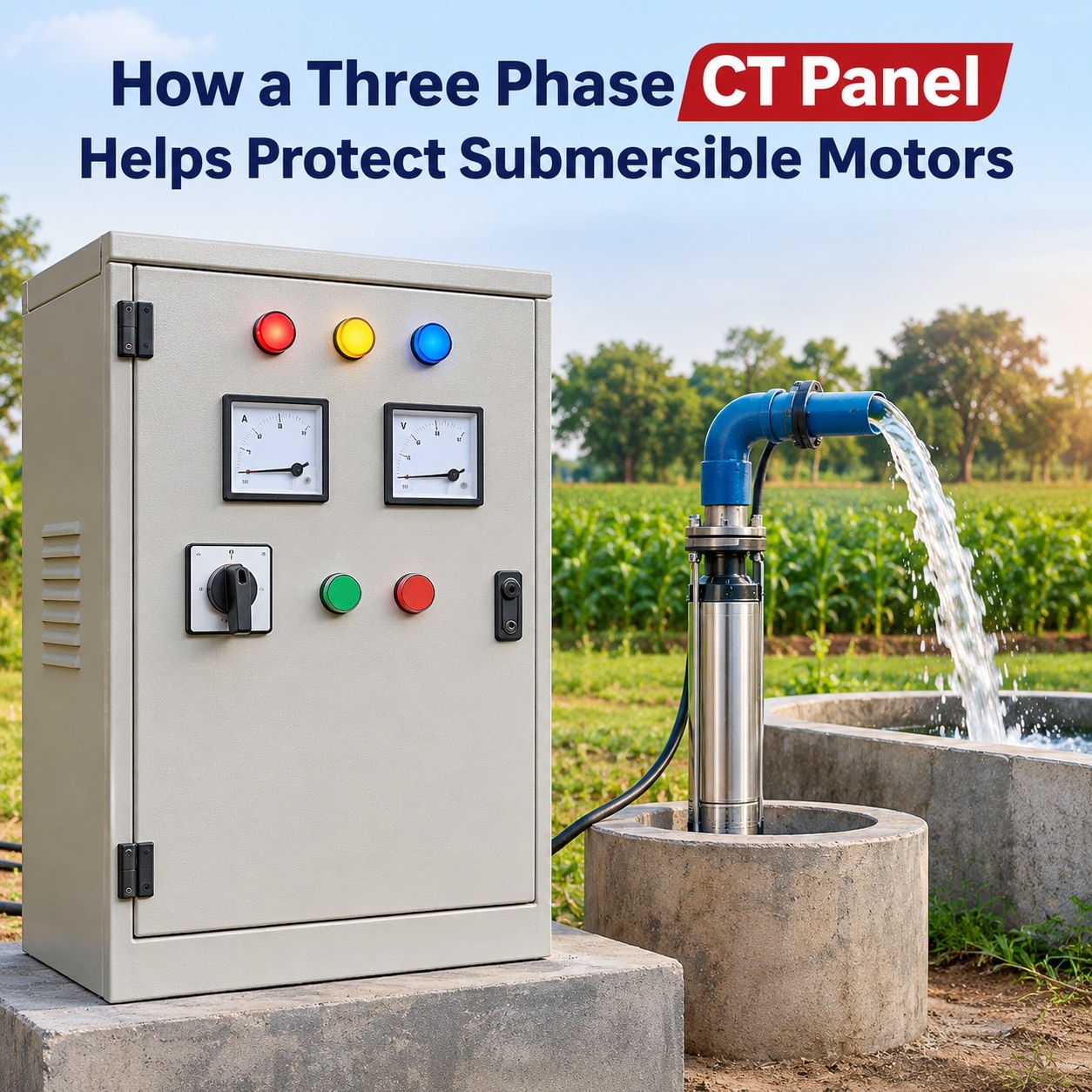
Each phase conductor passes through a current transformer (CT). The CT produces a smaller signal proportional to that phase’s current for a relay or ammeter, allowing the controller to compare all three currents instead of treating one average as the motor’s condition. These are core three-phase CT panel benefits for submersible motors in Coimbatore.
| Condition | What the CT comparison reveals | Likely response |
|---|---|---|
| Sustained overload | All three currents remain above the motor’s normal load | Overload trip prevents prolonged heating |
| Missing-load phase | One phase carries little or no motor current | Phase-loss trip |
| Severe imbalance | One phase differs sharply from the others | Imbalance or negative-sequence trip |
| Undercurrent | Current falls below the set running value | Dry-run or loss-of-load trip |
Unequal phase currents create negative-sequence current: a reverse-rotating magnetic component that increases rotor heating even when the average current looks acceptable. A voltmeter checks phase-to-phase supply voltage, exposing supply loss or voltage imbalance; it cannot prove that the motor draws equal current.
Before restarting, record all three phase currents, compare them with one another and with the motor nameplate current, then investigate any difference. A CT panel does not directly measure winding temperature, insulation resistance, water level, or earth leakage unless separate sensors or relays are installed. Never leave an energized CT secondary open.
Use shorting links or test terminals before removing a meter or relay.
Which protection responds to each pump and motor fault
A fault-to-device map prevents you from buying a CT relay and assuming every motor hazard is covered. The practical three phase ct preventer panel advantages appear when each protection function is matched to the failure it can actually detect.
| Fault | Primary response | What happens |
|---|---|---|
| Phase loss or blown fuse | Phase-failure relay and CT preventer | The voltage relay detects missing phase voltage; unequal or missing motor current makes the CT function trip. CT monitoring can still identify a blown fuse when residual voltage remains. |
| Phase reversal | Phase-sequence relay | It checks rotation order before starting. A CT relay does not replace this voltage check. |
| Current imbalance or sustained overload | CT preventer and thermal overload relay | The CT relay reacts to abnormal phase current. The thermal relay models heating and trips after a delay. |
| Winding fault | Short-circuit device, then overload coordination | Rising fault current requires a correctly rated MCB, MCCB, or fuse with adequate interrupting capacity. The CT relay and contactor do not clear high short-circuit current. |
| Pump jam | Short-circuit or overload protection | A locked rotor produces high current; coordinate instantaneous clearing with the overload delay. |
| Dry running | Undercurrent logic plus delay, or a sensor | Reduced water load often lowers current. A level probe, pressure sensor, or dedicated dry-run sensor gives stronger confirmation. |
| Earth fault | Residual-current or core-balance CT | Three phase CTs alone are not a complete earth-fault scheme. |
A single-phase preventer targets loss of one phase, not complete three-phase protection. A thermal overload relay also cannot detect dry running or phase rotation, so confirm every function and its start-up delay before purchase.
How to set CT and overload protection for a 10 HP motor
Do not set a 10 HP motor’s protection from horsepower alone. For 10 HP submersible control panel protection, read the nameplate voltage, full-load current, frequency, service factor, starting method, and permissible voltage range first.
1. Use the nameplate full-load current as the overload reference. Ten horsepower equals about 7.46 kW of mechanical output; at 415 V, 0.85 efficiency, and 0.80 power factor, the calculated current is about 14.4 A. That is an example, not a universal setting.
2. Select a CT ratio suited to that nameplate current and the relay input range. Check the CT accuracy class, rated burden, relay burden, and wiring length together. An oversized CT loses resolution at normal load; an undersized CT can saturate during starting and cause nuisance trips.
3. Set the overload relay to the nameplate current, following the motor manufacturer’s instructions and the selected IEC trip class: 5, 10A, 10, 20, or 30. A higher class allows longer acceleration but extends thermal stress during overload.
4. Confirm the relay provides phase-imbalance or negative-sequence protection with a stated percentage setting. Also verify a start-up inhibit or delay so locked-rotor current does not trip running protection.
5. Observe stable, normally loaded current before setting undercurrent. Dry running can reduce current, but throttled discharge, blockage, voltage variation, and near-shutoff operation can look identical. One analog ct pump panel benefits is direct comparison of all three currents during commissioning; add a level or pressure sensor when that evidence is unreliable.
How DOL, star-delta, analog CT, digital, and auto-start options differ
Choose DOL when simple wiring and easy troubleshooting matter more than starting surge. Its locked-rotor current can cause a large voltage dip, making it unsuitable for a long borewell cable, weak utility supply, or a 10 hp motor that cannot tolerate the surge.
| Option | Main difference | Choose it when |
|---|---|---|
| DOL | Simplest starter and fault tracing; high starting current | The supply, cable voltage drop, and pump system accept the starting surge |
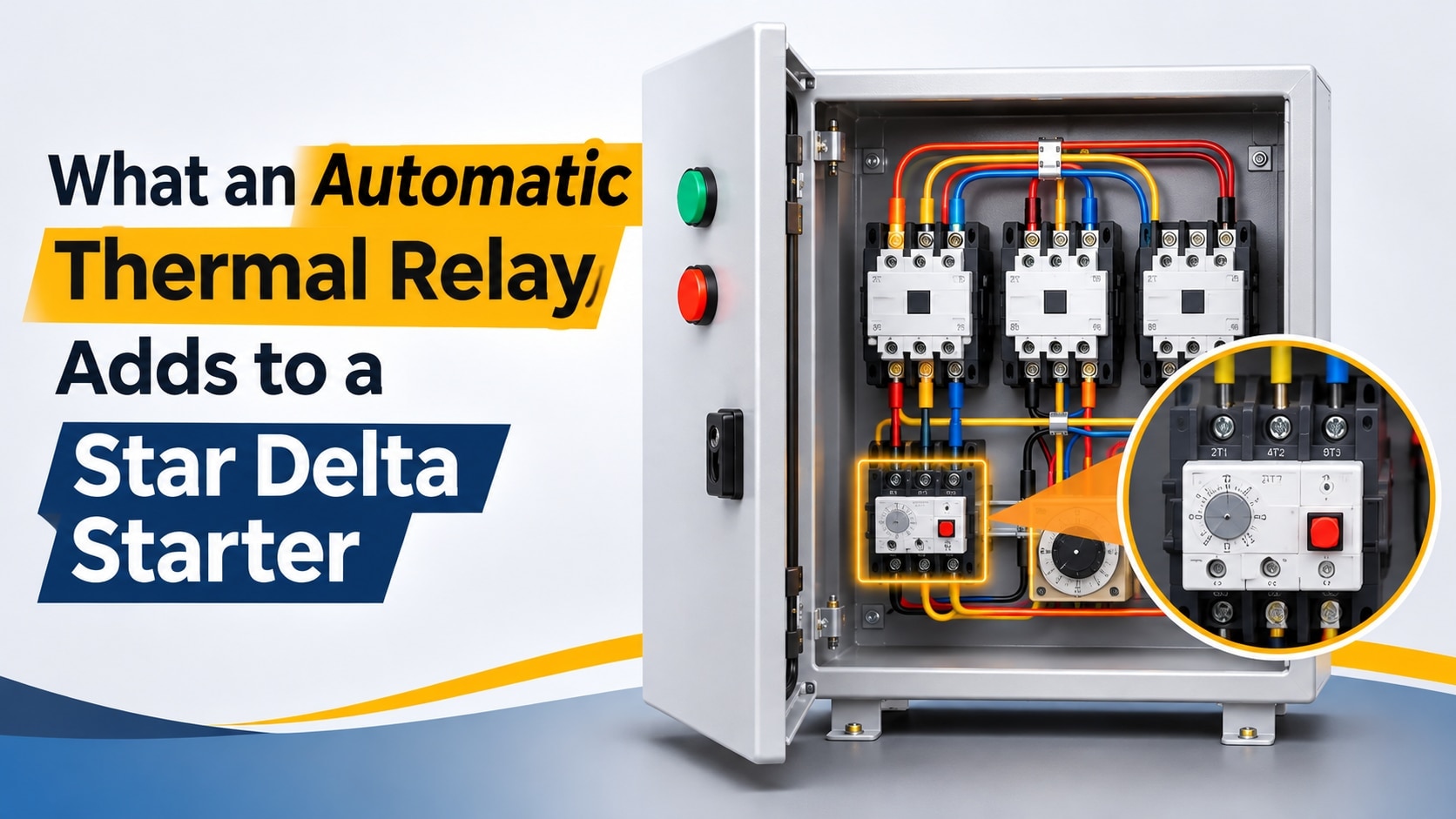
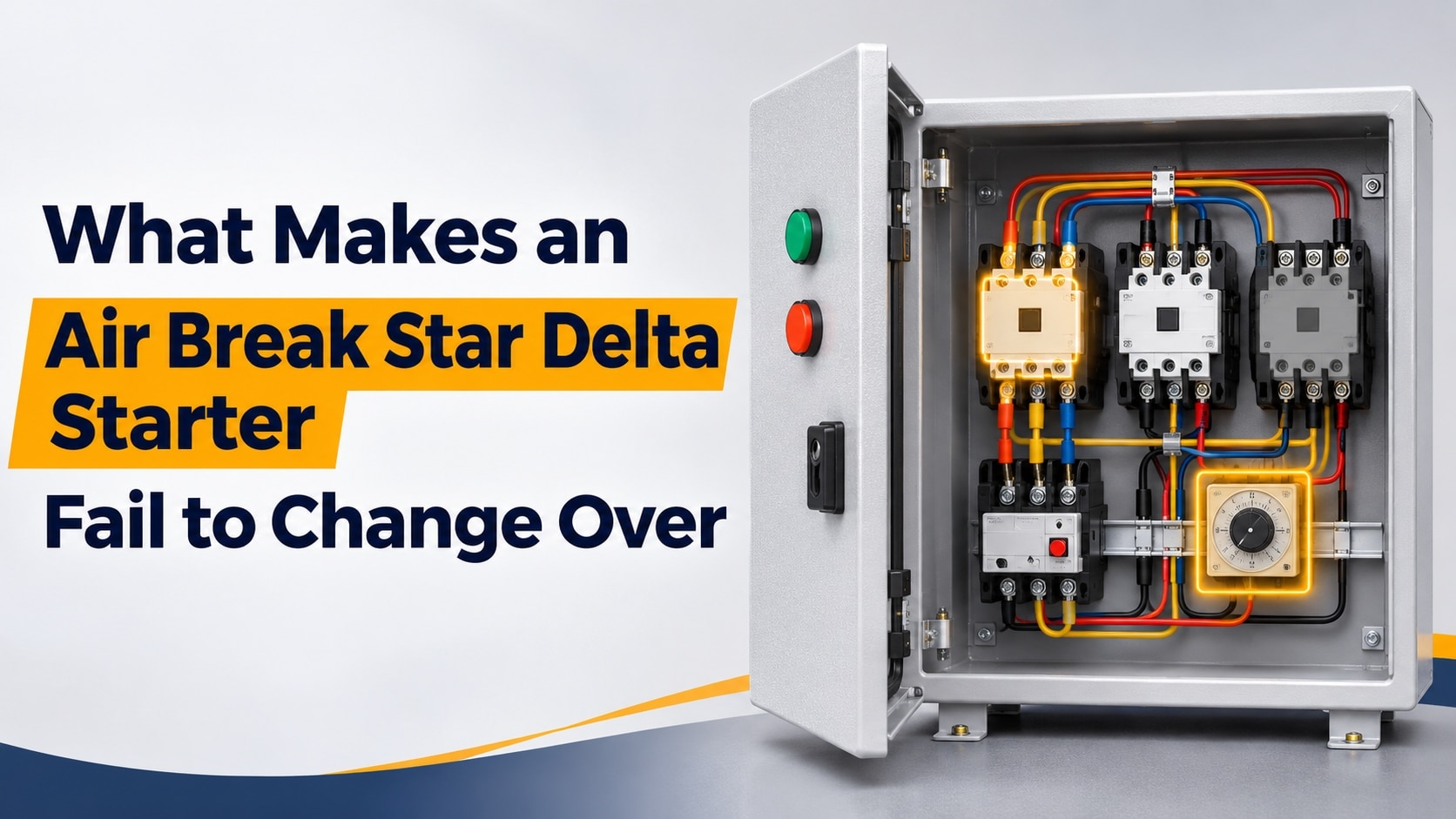
| Star-delta | Reduces current after changeover; needs six motor leads, timed contactors, interlocks, extra space, and transition testing | The motor and pump permit star-delta, including ratings above some CT panel ranges |
| Analog CT | Shows all three running currents immediately for commissioning and baseline comparison | You need visual detection of imbalance, overload, missing load, or changing current |
| Digital relay | Adds stored faults, adjustable thresholds, and clearer fault information | You need event history and more detailed diagnosis |
| Auto-start | Adds operating convenience, not motor protection | The pump needs automatic operation, while separate overload, phase, short-circuit, and dry-run protection remains installed |
For 10 hp submersible control panel protection, match voltage, nameplate current, starting method, phase sequence, cable length, voltage drop, supply fault level, pump duty, and DOL acceptability. Also check CT ratio, accuracy class, burden, relay input range, enclosure ingress protection, and control-circuit surge protection. Auto-start does not replace these safeguards.
The three phase ct preventer panel advantages are clearest when you need direct current comparison, while a digital relay suits fault history. MAG STARTERS (PRAVIN ENGINEERING) - 08048068970 is one local option to compare by these specifications, not horsepower alone.
Related products
 | SUBMERSIBLE CONTROL PANEL THREE PHASE ANALOG CT PREVENTER PANEL 10 HP ₹7060 Features: Ranging from 2 HP to 12.5 HP Suitable for Bore-well Submersible Pumps Analog Type Amps Meter & Volt Meter (Big-Square Type) Bimetal Thermal... View product → |
SUBMERSIBLE CONTROL PANEL THREE PHASE PANEL ANALOG +AUTO START 10 HP ₹7960 Features: Ranging from 2 HP to 12.5 HP Suitable for Bore-well Submersible Pumps Analog Type Amps Meter & Volt Meter (Big-Square Type) Bimetal Thermal... View product → |
How to prove the panel will trip before commissioning the pump
Do not approve the panel because its contactor energises. With the motor isolated, prove that measured current produces the correct protection response before connecting the pump.
1. Inject known current into each CT circuit, one phase at a time. Check every phase indication, CT ratio against the installed CT markings, polarity, phase mapping, overload pickup, undercurrent pickup, phase-loss response, trip delay, contactor drop-out, manual reset, and alarm output.
2. Confirm the relay’s start delay or inhibit exceeds the motor’s normal acceleration time. Otherwise locked-rotor current can cause a nuisance overload or undercurrent trip. Check CT secondary burden and cable length, especially on long borewell runs.
3. Inspect earthing, insulation resistance, cable size, terminations, voltage drop, enclosure ingress protection, voltage imbalance, and control-circuit surge protection. Test the selected MCB, MCCB, or fuse separately for rating and interrupting capacity; CT testing does not prove short-circuit protection.
4. During a controlled run, measure phase-to-phase voltage and all three phase currents at startup and stable load. Record the baseline, then confirm that dry-run protection has a level probe, pressure sensor, or dedicated controller when current-based undercurrent logic is unreliable.
These checks show the analog ct pump panel benefits during commissioning through immediate current comparison. They also demonstrate three phase ct panel benefits for submersible motors in coimbatore, where cable length and supply variation can expose installation faults. Approve the pump only when current, delay, and trip action match documented motor conditions.
Frequently asked questions
What does a CT measure before a submersible motor is damaged?
A CT measures each phase current separately, allowing the relay to identify overload, phase loss, current imbalance, and abnormal running conditions.
Which protection responds to each submersible pump and motor fault?
Short-circuit protection clears high fault current, overload protection responds to sustained excess current, phase-loss protection detects a missing phase, and dry-run protection responds to low-load or no-water operation when the panel supports it.
How should CT and overload protection be set for a 10 HP motor?
Read the motor nameplate full-load current, confirm the CT ratio and relay input range, then set overload protection to the manufacturer’s specified current rather than estimating from horsepower alone.
What is the difference between DOL, star-delta, analog CT, digital, and auto-start panels?
DOL provides simple full-voltage starting, star-delta reduces starting current, analog CT panels provide current-based protection with simpler controls, digital panels add display and fault records, and auto-start panels add automatic pump operation.
How do you prove a CT panel will trip before commissioning the pump?
Check CT wiring and phase sequence, inject or simulate the required fault conditions, verify each relay trip and contactor drop-out, record trip times and settings, then test the complete control circuit before energising the motor.
Keywords